Dynamometer
Design and development of a combustion powertrain dynamometerDesign goals
- To evaluate the characteristics of the KTM 500 EXC engine by measuring the power and torque at the crank of the engine.
- To acquire, analyse and apply the output characteristics of the engine in further optimizations and calculations like engine performance, intake-exhaust simulations, fuel consumption calculations, etc.
Calculations
KEY
- PE/1 = Instantaneous Power of Engine
- τE/1 = Instantaneous torque of Engine
- ΩS1/1 = Instantaneous Angular Velocity of Crankshaft
- αS1/1 = Instantaneous Angular Acceleration of Crankshaft
- δT = 1/Frequency of reading of CAM sensor
- IE/IS1 = Moment of inertia of Crankshaft
PE/1 = τE/1× ΩS1/1
τE/1 =( IE + IS1 ) αS1/1
αS1/1 = dΩ/dt~δΩ/ δT~(Ω2 - Ω1)/(T2-T1)
δT= 2π/(avg(Ω1, Ω2) ×number of teeth on trigger wheel
Ω1, Ω2 are known from the sensors
δT is known
Hence αS1 is also known.
Components Used:
- CAM position sensor
- Engine test bench
- Arduino
Design Process
- Manufacturing
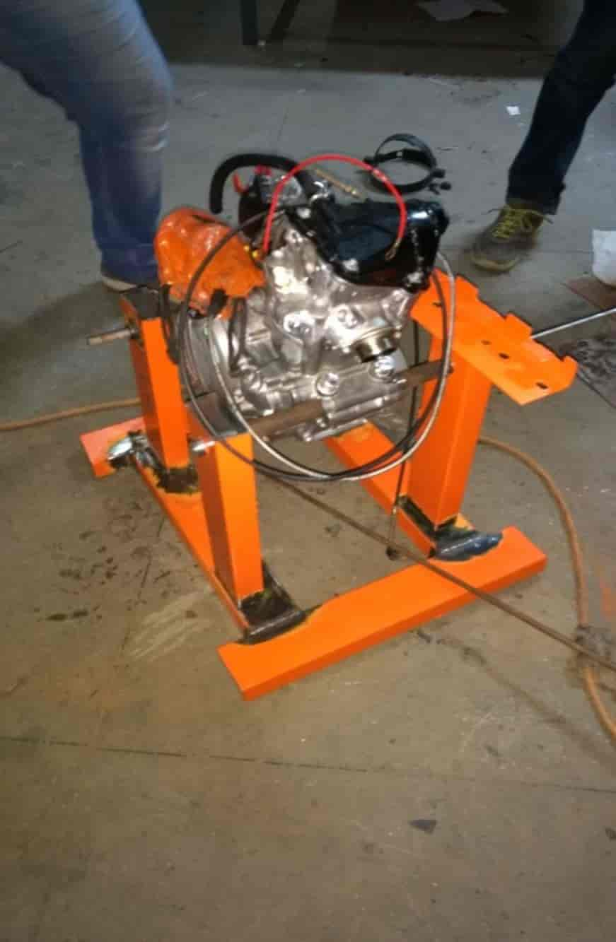
- A CAD model of the structure was made using the SolidWorks 3D designing software.
- The test-bench was then manufactured using mild steel tubes and the engine was successfully mounted on it.
- Selecting Microcontroller
- The next step was to find a microcontroller for acquiring the real-time output of the engine sensors. This would include the instantaneous RPM (rotations per minute) and angular acceleration values.
- After detailed research and analysis, it was decided that using the Arduino Genuino/Uno R3 microcontroller would be apt and suffice our needs.
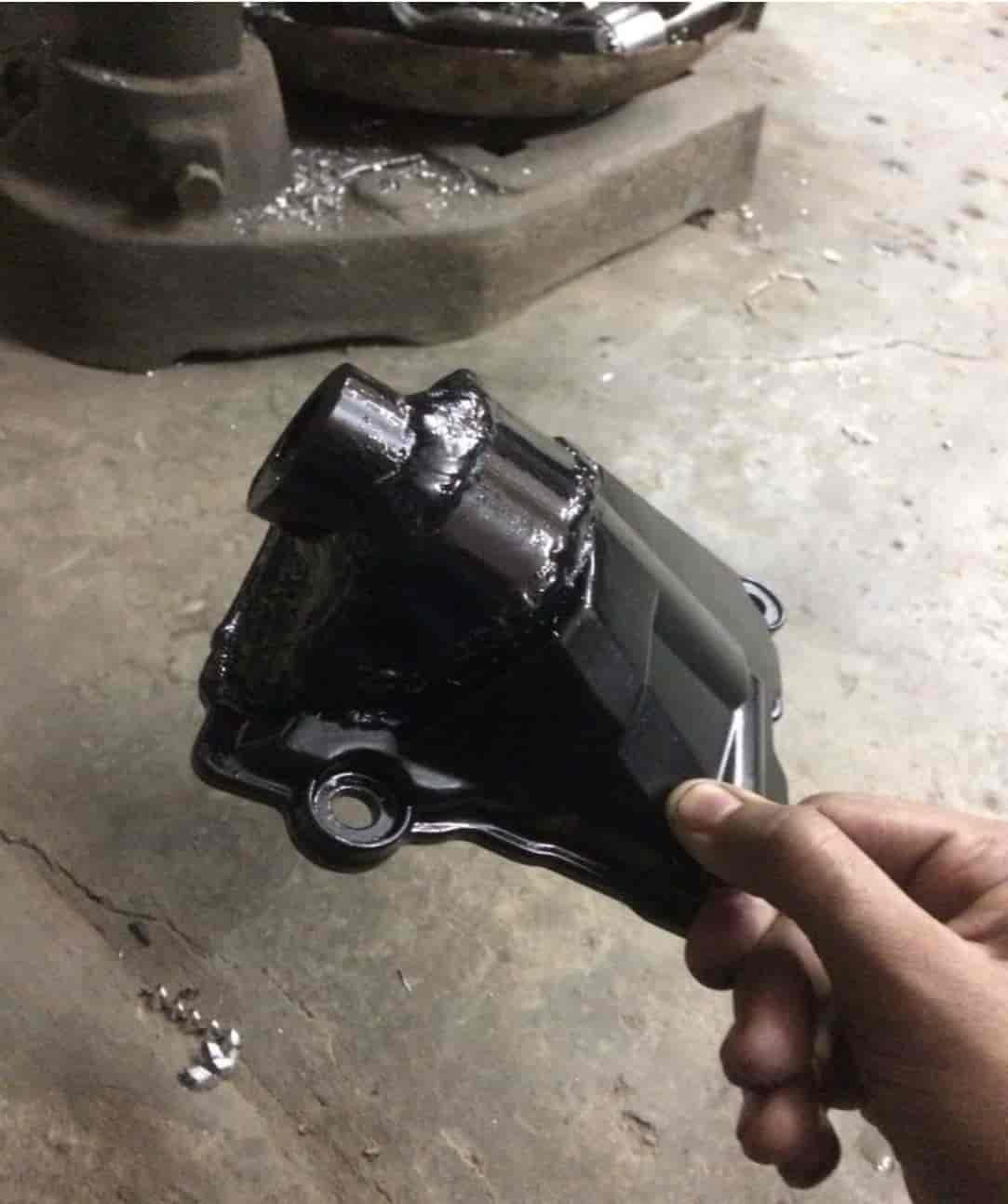
- Mounting the sensors
- A variable reluctance magnetic sensor for identifying the rotations per minute of the camshaft was purchased.
- This sensor was securely mounted on the engine head such that the rotations of the camshaft could be accurately identified.
- Reading Sensor Data
- An Arduino Sketch for reading the analog voltage signals of the camshaft sensor was written and the incoming data was critically analysed
- Arduino Sketch was repeatedly altered to directly input the realtime RPM of the running engine. It is to be duly noted that these experiments were being carried out on the engine mounted on the dyno-bench without any load (inertial mass) coupled with the engine.
- Verifying Results
- The results of the experiment were cross-checked by evaluating the RPM of the engine using an ELM 327 On-Board Diagnostics 2 (OBD-II) tool
- The tool was paired up with a phone via Bluetooth to the ECU. Owing to the meticulous accuracy of the instantaneous RPM from the Arduino Uno microcontroller unit, the obtained results were then used to calculate the instantaneous angular acceleration of the running engine.
- Developing the application
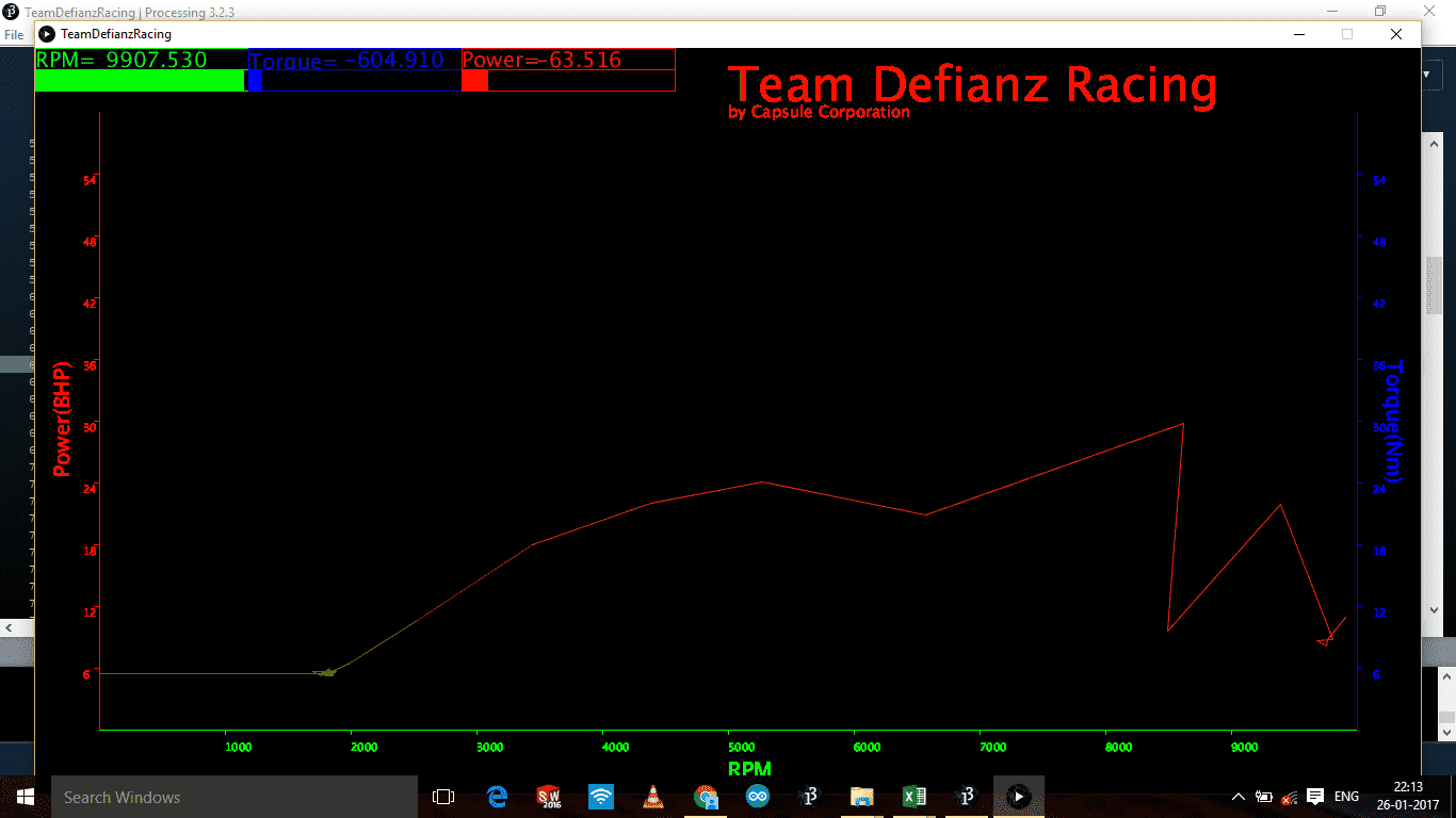
- To further improve on the data evaluated, the real-time values of RPM and alpha (angular acceleration) were used to plot RPM vs. angular acceleration graphs using Processing 3.0 visual software.
- Since, the output power of the engine is directly proportional to the instantaneous angular acceleration, the graphs obtained were thereafter analysed to understand the relation between the instantaneous RPM and power of the KTM 500 EXC engine
Dynamometer Iteration 2:
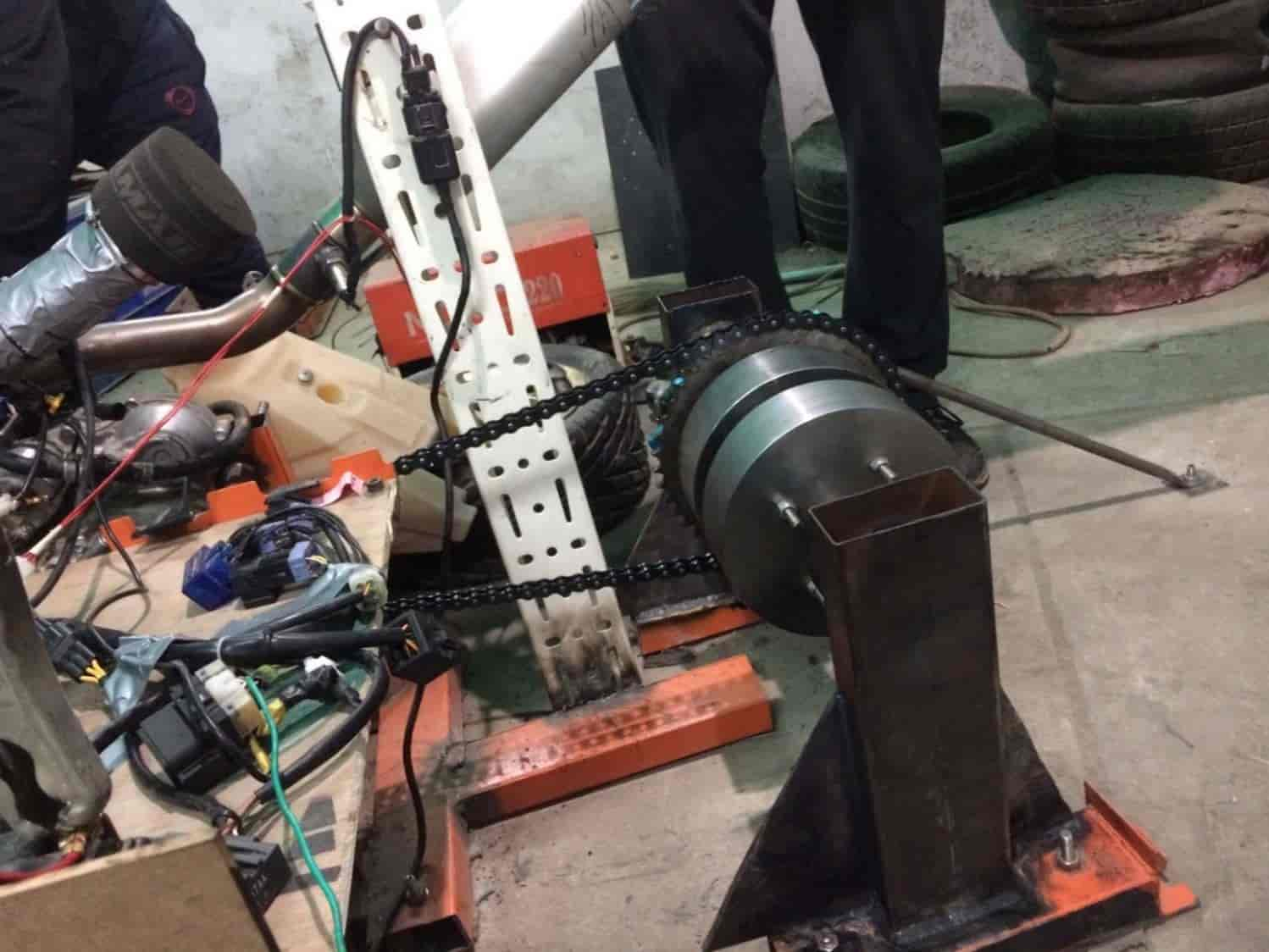
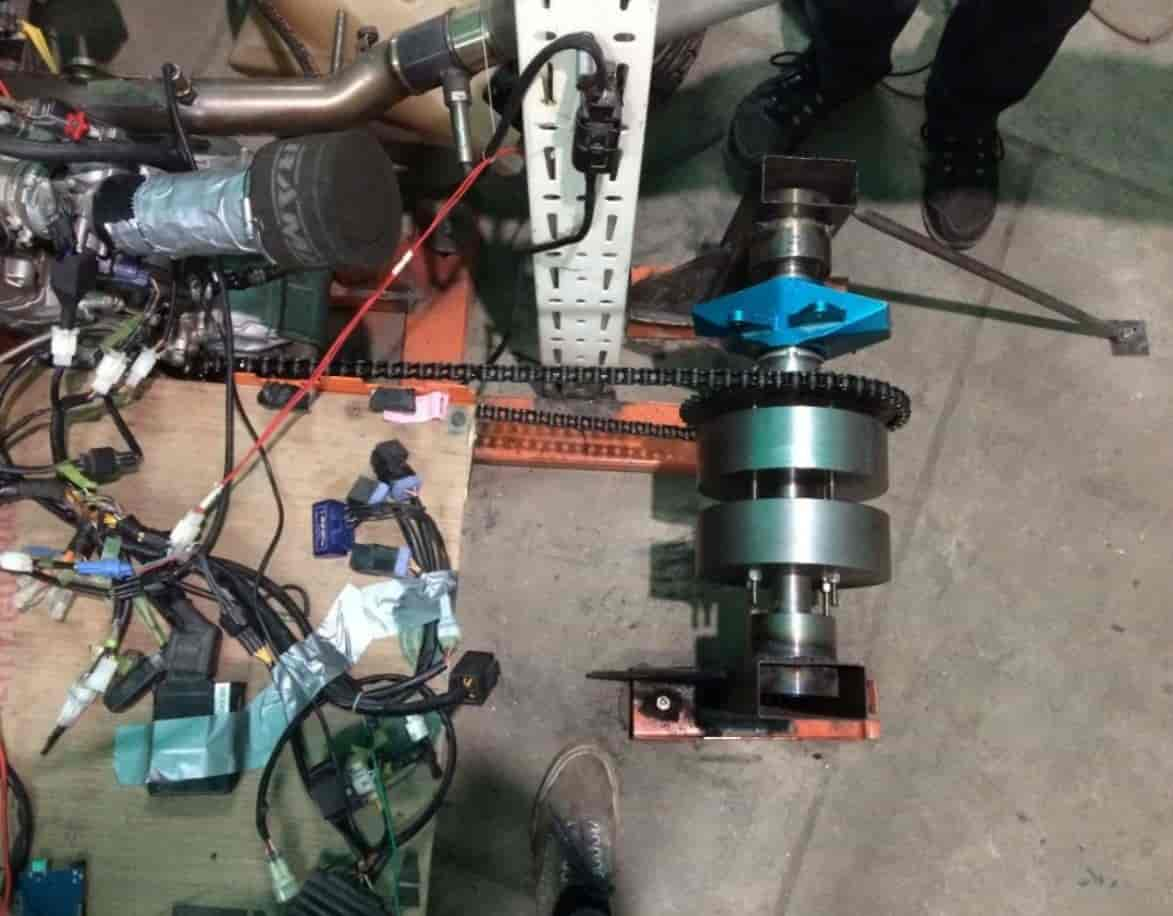
- Once all the basic setup was complete on the dynamometer, second phase of development was started which included an inertial mass driven by engine power through chain drive.
- Pillars were erected for mounting the shaft onto which the solid cylinder was to be mounted.
- In order to couple the inertial mass with the engine, a sprocket of 5.9 mm thick mild steel was manufactured by the aid of a CNC wire cutting machine.
- Roller bearings at both ends of the shaft facilitated the shaft’s rotatory motion.
Dynamometer Iteration 3: (In Development)
- The third phase of manufacturing included mounting a brake to the dynamometer to vary the load on the engine according to the requirement of the operator.
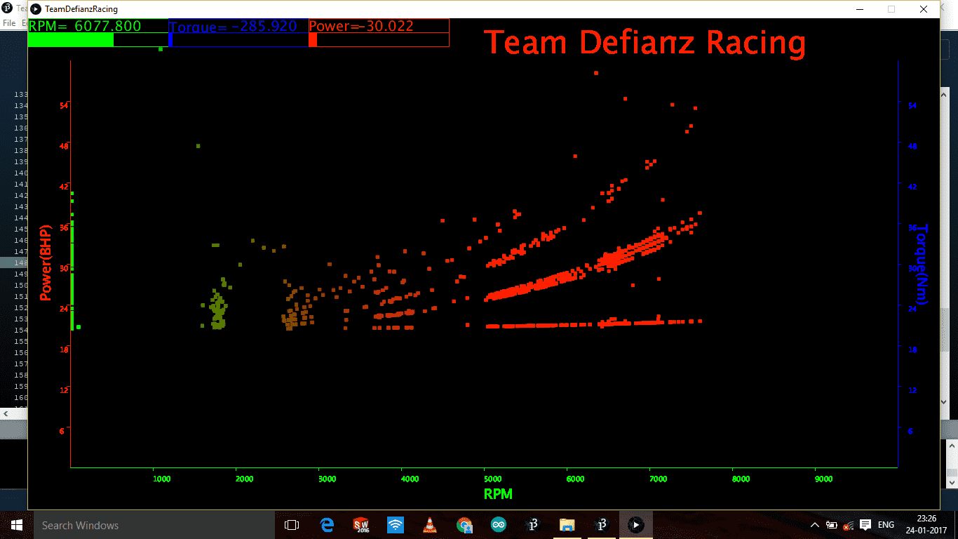
- The braking torque will be measured by the load cells connected to the upright via a rod, transferring braking force to the ground. The whole assembly was brought together and the experiments were carried out again to measure the instantaneous RPM and angular acceleration of the engine. In essence, the amount of load on the engine could be varied by the extent to which the brake pedal was pressed. Hence, we were able to increase the number of data points and plot clear-cut precise RPM vs. angular acceleration graphs – enabling us to critically analyse the characteristics of the engine.
Testing Engine Dynamometer