Variable geometry intake manifold
Design and development of a variable geometry intake manifoldIntroduction
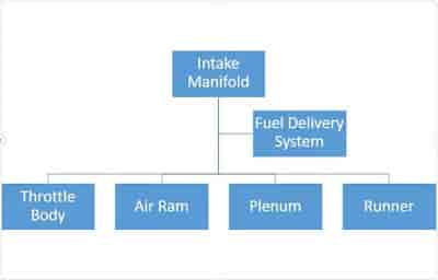
An intake manifold is simply a mechanical component attached to the engines cylinder head that allows the air/fuel mixture to enter the combustion chamber of the engine. The intake manifold consists of following parts:
What is Variable geometry intake manifold?
Short answer, to achieve greater Volumetric efficiency. As a consequence of greater volumetric efficiency, we can achieve greater torque, power and thermal efficiency from the same size of the engine at the same RPM.
What is Volumetric efficiency?
Volumetric efficiency in an internal combustion engine, is defined as the ratio of the mass density of the air-fuel mixture drawn into the cylinder at atmospheric pressure (during the intake stroke) to the mass density of the same volume of air in the intake manifold.
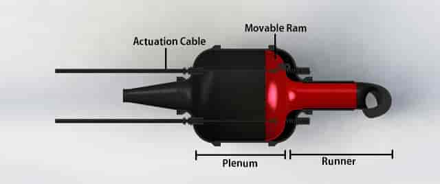
Variable geometry intake manifold:
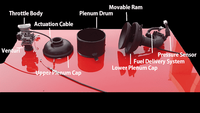
The design consists of the following components, arranged in the direction downstream to the air flow:
Design: The design consists of the following components, arranged in the direction downstream to the air flow:
- Throttle Body: Contains the throttle position sensor and connects the butterfly valve to the throttle actuation cable.
- Venturi (Or air restrictor in case of FSAE): The smallest path in the intake manifold.
- Actuation Cable: connects the Movable Ram to the servo.
- Upper Plenum Cap: makes the upper part of the plenum and contains the mounts for actuation cable and pressure sensor. It connects to the plenum drum via screw threads.
- Plenum Drum: Connects the upper and lower plenum.
- Movable Ram: Moves inside the plenum drum to control the plenum volume and runner length.
- Lower Plenum Cap:makes the lower part of the plenum and contains the mounts for actuation cable and pressure sensor. It connects to the plenum drum via screw threads.
- Pressure Sensor: Is used to measure pressure at different parts of the intake.
- Fuel Delivery system: Made up of fuel injector and fuel delivery lines from the fuel tank.

Specifications
- Throttle body size: 28mm
- Venturi Diameter: 20mm (FSAE rule restricted)
- Plenum Volume: Variable(1200cc to 2800cc)
- Runner Length: Variable(230mm to 330mm)
- Runner Diameter: 40mm
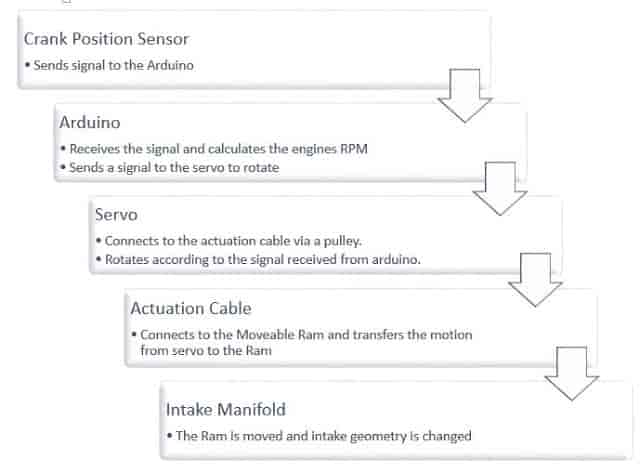
Working overview
Unfortunately, I lost all the videos and images of the setup in a corrupt memory card. All that is left is an amateur video of the setup below:
Mechanism
Below images describe the movement of the movable Ram and the corresponding change in the geometry of the manifold
- As the Ram moves towards the upper plenum cap, the plenum volume is decreased and the runner length is increased. Both of these changes enhance the bottom-end(Low RPM) performance of the engine.
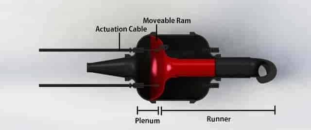
- As the Ram moves towards the lower plenum cap, the plenum volume is increased and the runner length is decreased. Both of these changes enhance the top-end(High RPM) performance of the engine.
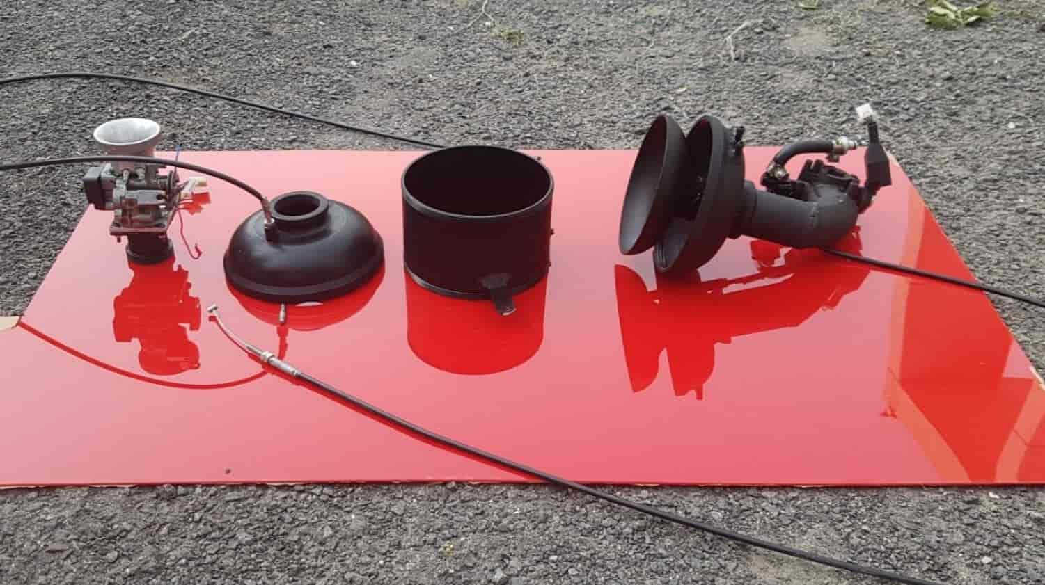
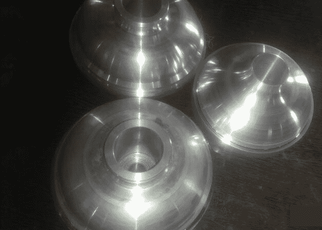
Manufacturing
- The manifold was manufactured primarily on a CNC Lathe machine and a CNC Vertical milling machine.
- The material selected was aluminium due to light weight, corrosion resistance and good weldability.
- Below is a picture of the machined components.
Why not 3D printing?
Some may argue in favor of 3D printing the manifold instead of CNC machining. And to some extent their argument may be valid and legit. But the reason that I chose the latter is because of my previous experiences with 3D printed intake manifolds. The problem with 3D printed manifolds, is that the designs are too rigid. By that I mean, that making changes to an already manufactured manifold is kinda impossible. For example, if you later want to add an extra pressure sensor or temperature sensor to the manifold, you'll need to make some sort of mount on the 3D printed part. And to make a mount, you'll need to machine it, which is very limited on most 3D printed materials.
On the other hand, using aluminium allows for much more flexibility in the design. That is, on later stages if you want to make some addition to the design, aluminium allows for several machining processes, like welding, threading, knurling etc. which are in-existent in 3D printing.
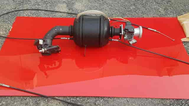
Assembly
The final assembled manifold looks like this:-
Validation
- Using the data acquisition system that we made earlier, pressure values were recorded in the intake manifold at different throttle percentages.
- This data was then plotted on MATLAB and analysed. An example of sample data and result is shown below:
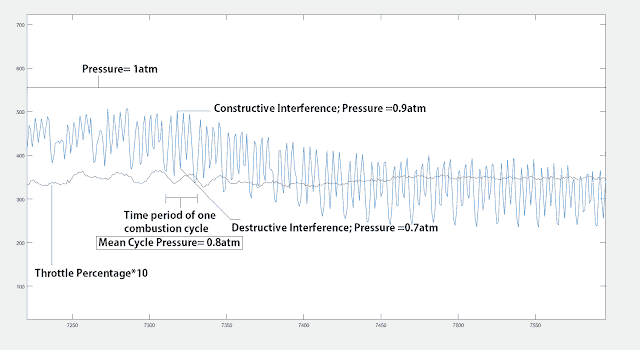
- Percent Increase in volumetric efficiency at constructive interference point:

Where,
Pc= Instantaneous pressure at that point
Pm= Mean pressure of that cycle

- Similarly, Percent Decrease in volumetric efficiency at destructive interference point:

- To put that in prospective, an engine with a fixed intake manifold, producing a mean of 40Nm of torque at say 8500RPM, can produce 45Nm simply by swapping a fixed intake manifold with a variable one.
Note
However, it is noteworthy to mention that the change in volumetric efficiency is very much inflated in our case. This is due to the air intake restrictor in the Formula student cars, that make even stronger pressure waves, specially at higher engine speeds. For road cars, the results will not be this inflated, as they have no intentional air restriction in their manifold. But still, a significant change of about 6-8% may be observed on road cars. Moreover, the above calculations, to its core, are not 100% accurate. For more accurate results, an integral of pressure wave function is to be considered over one suction cycle instead of mean values. This may further reduce the inflated value and will yield more accurate result.
Result
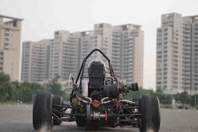
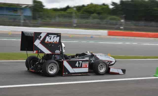
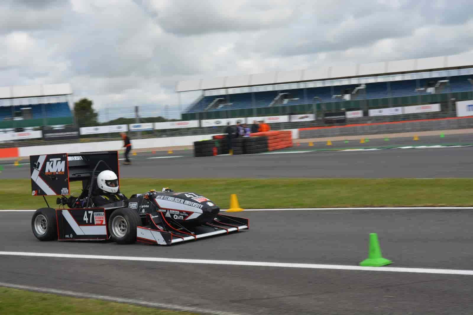
The result of such careful design of the intake manifold led to the making of a very competitive FSAE car.